
Tired of closing and opening your chickens? Going away for a vacation and don’t want to worry about predators getting in your coop? Then you can buy something like this automatic coop door. They have certainly come down in price and there are now a few competitors available. You would have a warranty to go to if something breaks and instructions to reference if needed.
BUT, if you ended up on this site, its probably because you are a bit engineering/DIY minded OR you just want to adapt this Arduino code to another project. The most expensive part of ANY door opening project is the linear actuator. The rest of the equipment is quite inexpensive and can be adapted to a wide variety of doors, whether for chickens, humans, shed, garage, platforms, or shade clothes for a boat.
DIY Chicken Coop Door Parts List
- Arduino Uno (~$13)(Larger Version will need 2 gang electrical box minimum OR Arduino Nano (~$7, but requires you to solder a bit) (Smaller Version, can fit in a 1-gang electrical box)
- Relay Blocks $7 (Double Relay Block – All you need) ( 10 Pack – Relays – useful . . . )
- Photo Resistor Board $10 for 10 (Since these are exposed to the elements it may be useful to have a backup)
- Linear Actuator 12V 6″ (length may be dependent on your door, These motors are slow but strong, so you can attach them close to the hinge(less distance) to make a bigger move for your door) This one lifts 55lbs and comes in at about $55. The longer the length or the stronger, the more expensive.
- Arduino Wires (these plug and play , but you could use scrap wire and solder if you know how)
- Soldering Iron (Optional, this is a cheap, but good iron I personally own) & Solder (again, very useful, but not necessary, This is quality solder, do NOT cheap out on solder)
- Electrical Wire Cutters (Optional) You could carefully use a knife, but I use electrical pliers at least 1x per week)
- Single Gang PVC Electrical box ($8) and cover ($2)(for a Nano) or Double Gang PVC electrical Box ($10) and double cover($3) – Fairly Waterproof
- Power Supply (I used an old 2 amp 5V phone charger (FREE) and it worked!! More info below) OR you will need a 12V power supply (for the linear motor to work at full speed) and an arduino step down transformer (to go from 12v to 5v for the arduino)
- USB Cable (OPTIONAL – because you could use any USB Type cable to supply power to the pins directly)(For arduino Uno Type A to Type B – Any printer cable from the last 20 years will work) (For Arduino Nano Type A to Mini – B)
- Scrap Wood (I used “used” ripped 2×4’s – 2×2’s basically as the frame and a piece of old 2×12 wood.
- Hinge ($4) – Link may change often, but can be scrapped from old items easily.
Prices are at time of writing (Totals from $80 to about $100 depending on how much scrap wood, wire, old power supplies you may have around you). This is about a 50% savings over the cheapest automatic coop door available on Amazon.
Arduino Chicken Door Instructions
I spent a lot of time thinking about the design of this because I wanted the whole setup to run from a single 5V 2 amp old cell phone charger (Notes on solar below). I was very excited when I was able to prove that the 12V linear actuator would run (albeit slowly) on a single 4.2 Volt lithium battery. This prompted some cutting of USB wires and proof that I could keep the motor running while maintaining power to the arduino with the old charger.
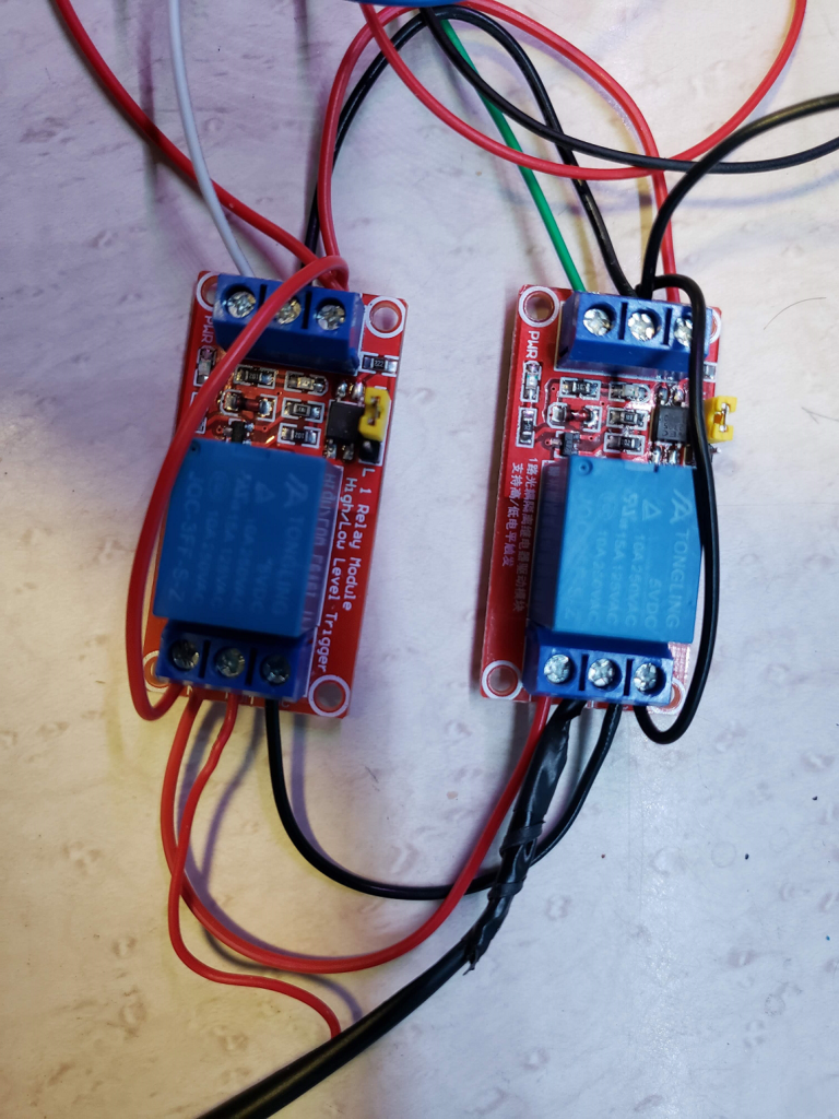
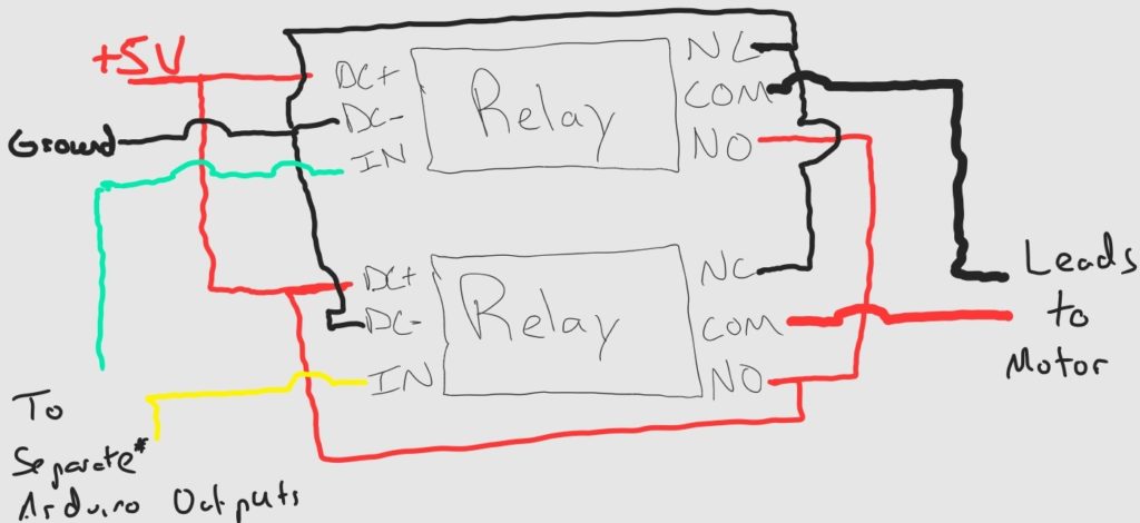
Step 1: Wiring the motor relays
Step 2: Arduino Wiring for Chicken Coop door
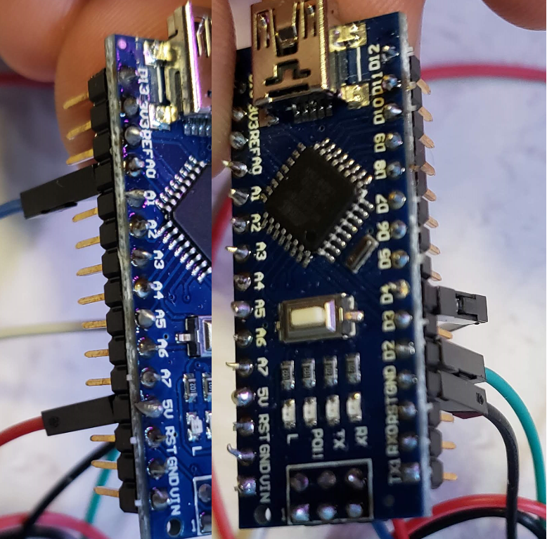
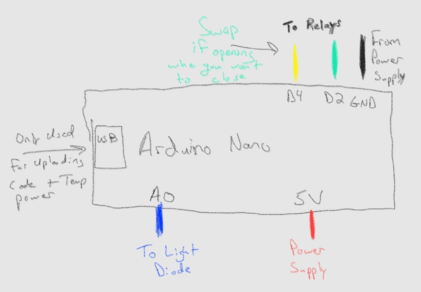
The arduino wiring is simple for this build.
- 5V + from power source, in this case the red wire from an old USB cable plugged into a 2Amp cell phone power brick
- GND – From power source, Black wire from spliced USB cable plugged into power supply
- A0 – Signal wire from Photocell (Usually noted by an S on the photocell board). Arduino reads the signal voltage and turns it into a number our code can use to decide whether to open or close the door.
- D2 – Signal to close one of the relays
- D4 – Other signal to close the other relay. If the behavior of your motor is opposite what you want, just swap D2 and D4
- NOTE that I discovered Arduino can’t power two relays with one output, not enough mA. I changed the design of my relay block to accommodate this and it ended up being much better for power saving.
Step 3: Photocell wiring & Common +5V/Gnd wires
Fairly straightforward, wire the + terminal to the +5v power supply, GND (-) to Ground, and S to the A0 Port of the Arduino. Cut the photocell off the board and extend the wires long enough that you will be able to put the sensor through a hole in the coop wall to test the light. Some photocell boards have a sensitivity adjustment screw, you may need to adjust this during your testing as well as the lightThreshold variable in the code.

Anywhere there was a red +5V wire you can twist them all together and solder or use electrical tape to bond them permanently (can be see in the photos)
Anywhere there was a black GND (-) wire you can twist them together and solder or secure with electrical tape.

Arduino Chicken Door Code (for Solar)
Download the Arduino IDE desktop App (More compatible in my experience), or you can use the Web Interface. Copy and paste the code below and plug in your Arduino to your computer. Click Compile then click upload.
If you encounter an error and it is your first time programming an Arduino, here are some helpful hints . . . Many arduino devices are knockoffs of the real thing(Mine was), so under the “Tools” menu, I selected “Arduino Nano” (Choose Uno if that is what you have) and for Bootloader I selected ATPmega328P (Old Bootloader). The Port will be dependent on your system, but should be detected automatically. Some knockoffs require a special driver be installed, but they usually come with the driver you will need.
I included lots more comments than most of these types of tutorials offer, but I’ve found that that is what makes my website worth visiting.
//This library came from github https://github.com/rocketscream/Low-Power#:~:text=%23%23%23%23Notes%3A%20External,order%20for%20it%20to%20work.  Download all files and put in your arduino libraries folder (Program FIles (x86)/Arduino/Libraries)
#include <LowPower.h>

  int closeRelayPin = 2;
  int closeRelayPin2 = 4;
  int lightSensorPin = A0;
  int analogValue = 0;
  int i;
  int lightThreshold = 400;    //Increase or Decrease this number to change the sensitivity of the light sensor.  400 was good for Dawn/Dusk for me, but keeps the door open during cloud cover and daytime storms.
  int doorSpeed = 60000;       //In Milliseconds, how long you want to leave the relays activated for.  Test how long it takes your door/motor to open or close in seconds then add 5 or 10 seconds and multiply by 1000.
  int sleepyTime = 225;        //Higher numbers sleep longer between light checks, lower numbers sleep longer.  225 is about 30 minutes (This saves a lot of energy!)  Each count is 8s of sleeping.
  bool closedDoor = false;

//Assigns pins on the arduino to our variables above
void setup() {
  pinMode(closeRelayPin, OUTPUT);
  pinMode(closeRelayPin2, OUTPUT);
}

//The program that arduino loops through as long as it has power
void loop() {

  //Reads the current light in the room
  analogValue = analogRead(lightSensorPin);

  //Checks if the door is open and if it is dark outside - If yes, then it activates the close door relay for 60 seconds
  if(analogValue < lightThreshold  && !closedDoor){
    digitalWrite(closeRelayPin, HIGH);
    closedDoor = true;
    delay(doorSpeed);
  }

  //Checks if the door is closed and it is light outside - If yes, then it activates hte open door relay for 60 seconds - Will NOT activate if the first condition was true, so the default is safety door closed
  else if (analogValue >= lightThreshold && closedDoor){
    digitalWrite(closeRelayPin2, HIGH);
    closedDoor = false;
    delay(doorSpeed);
  }

  //Turns off both relays
  digitalWrite(closeRelayPin, LOW);
  digitalWrite(closeRelayPin2, LOW);

//If you can't find the Low Power library or you are not worried about electricity savings, then comment out the For loop between this and the next comment . . .
//Loop that puts arduino in low power mode for an extended period of time
  for (i = 0; i <=225; i++)
  {
    LowPower.idle(SLEEP_8S, ADC_OFF, TIMER2_OFF, TIMER1_OFF, TIMER0_OFF,
                 SPI_OFF, USART0_OFF, TWI_OFF);
  }

//Stop deleting here to remove the Power Saving.

}
When you first test your door and setup you will want to set the “sleepyTime” variable to something much less than 225 so that you can observe the behavior of the door and test your connections. Once you confirm that the door is working as expected, change the number back to 225 so that power is saved and the arduino only wakes every half an hour to check the light.
ANY changes you make to the code must be Compiled and uploaded until you are done testing.
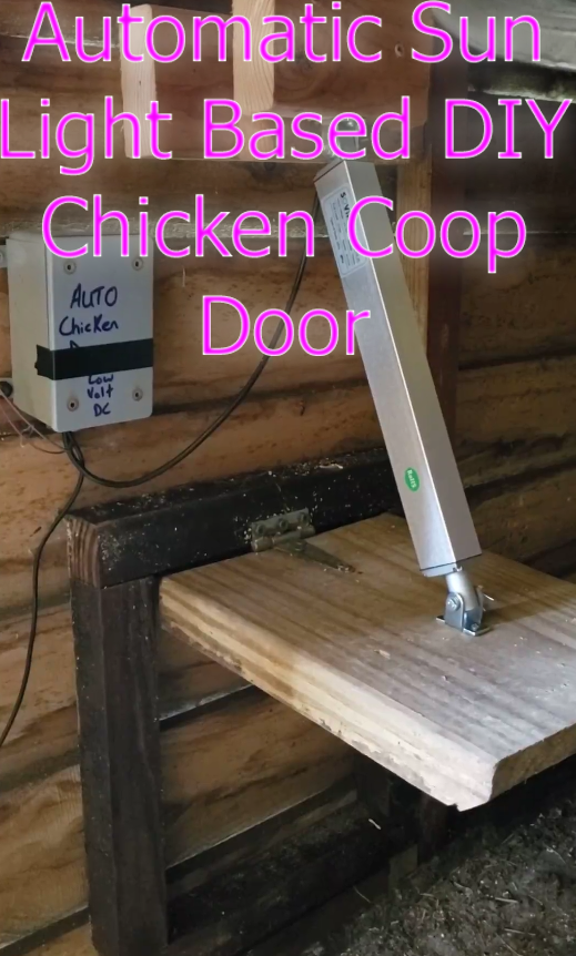
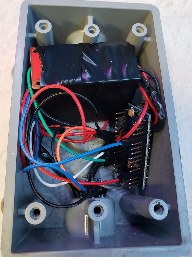
Final Step – Make it pretty and protect it from moisture/Chicken Poop
That last step is to hide everything in a PVC (so as to avoid electrical shorting) Electrical box as can be seen in the video and the pictures below. I didn’t have a spare mini Type B USB cable, but it may have been useful to leave one connected to the board and dangling outside the box in case I need to make any changes to the code in the future, though I find that very unlikely.
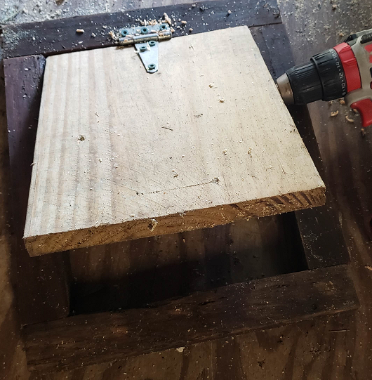
Other Final Step: Make a door . . .
This is actually optional as it depends on your coop. If you have a good free swinging door on your coop already, you can attach the linear actuator to it. These actuators are very strong. It takes some experimentation to decide where to put the brackets. I chose to make a separate door that my wife and kids would be able to go in and out of as they please. In the video I had not cut out the wall yet because I want to prove it worked first.
Optional Extensions
- Override Button – Buy or scrap a momentary push button (called Normally Open). Attach one wire from the button to the ground source and the other end to the relay (IN) port. Do not disconnect the wire from the arduino. Holding the button down will manually bypass the arduino and power the open circuit. If it doesn’t work you may have just selected the wrong relay.
- Door Open/Closed status – We happen to already have a SmartThings home so it was easy to use a contact sensor attached to the coop door and make a rule that when it opens/closes to turn on a light in our home. We actually used the led under cabinet lights in the kitchen that light up purple so we know it was the coop and the chickens are safe or out for the day.
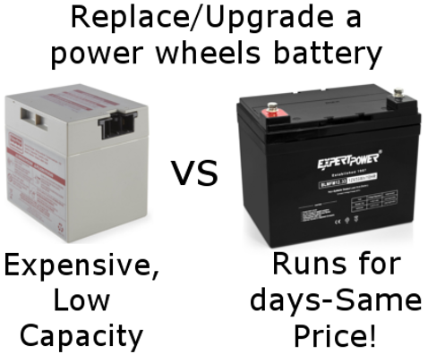
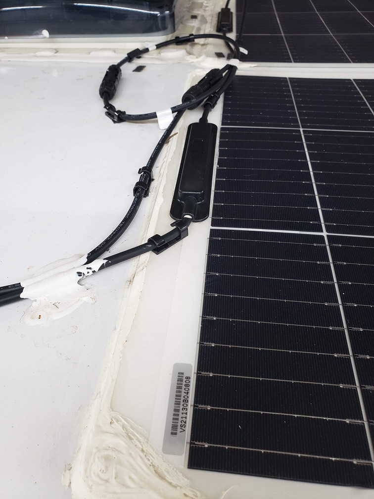
- No power – No Problem – Solar Adaptation – You’ll need a battery (small, even a lawn mower battery would work since the charge should stay topped off), a solar panel (This 100Watt panel is extremely overpowered, but that may serve other functions in a coop . . . A 20 watt panel should be enough to balance, but I couldn’t find one), and a solar charge controller(Whoa, these have gotten cooler since I last looked into them . . . This one has two USB ports you could plug and play with the design I made above). The Arduino spends most of the day sleeping and no Relays remain activated at any time, so it is configured to be very low power. The charge controller I linked to above also solves the problem on stepping down the voltage since it has 5V ports on it already. You could also hook the relay block directly the battery power to make the motor work much more quickly.
Conclusion – Thoughts
You can use this same set up to open any door, put up a boat canopy, etc. All you would need is a set of relays and a big enough power supply, the brains (the Arduino and code) would not be changed much)
I hope this gets a good reception online as I had a lot of fun building and sharing this DIY Chicken Coop Sun Light Sensing Door. I know there is still a lot of variability in each application, but I hope that I have inspired some of you become Makers! Please leave a comment below if you have an idea for another arduino project you would like to see!
Ah yes, I am also supposed to tell you that the Amazon links included in this article are affiliate links. This does not change the price for you in any way, BUT if you make a purchase within 24 hours of clicking my link, I get a small percentage of Amazon.com’s profit. That percentage helps me to run this site and fund future projects. I thank you for using the links!

